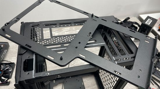
In this guide, we’ll show you how to move your motherboard tray to a different place in your case. There are precious few modular cases available that allow you to move key components such as motherboards. Drastically altering your case’s internal layout might sound like a nightmare, but it’s actually nothing a Dremel, rivet gun, and a couple of hours of modding can’t handle.
In return, you’ll be able to build a gaming PC exactly as you want it. You can gain lots of space to house fans and radiators if you want to water cool your PC, while getting increased clearance for other components. You can even invert your motherboard tray to further benefit your specific layout. In our example, we’re using a Cooler Master NR200P case as the test subject.
1. Decide on goals
Start by deciding exactly where and why you want to move your motherboard – focusing on one or two aspects can help to get the most out of the result. Here we want to shift it to the middle of the case, switching to a sandwich-style layout, while also moving it down to make room for a radiator.
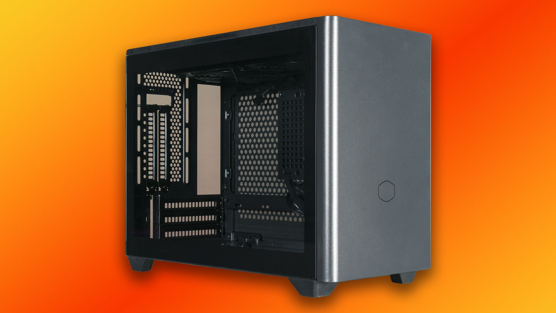
2. Remove fixtures and fittings
It’s important to remove any components that don’t make up the structural part of the case, as these can prevent you from removing other sections, or they can simply get in the way. Remove every part you can, but take note of the parts you’ll need to replace afterward.
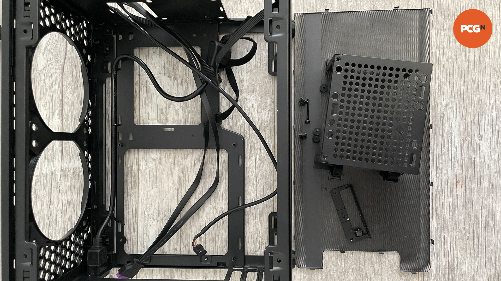
3. Remove cables
As there will be lots of dust and metal shards flying around, you need to remove all cables, such as those for the power and front panel ports. This way you won’t have to waste time cleaning (or repairing) them later.
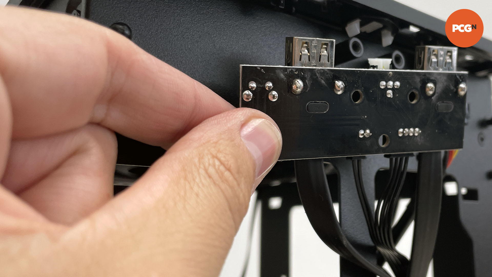
4. Install final components
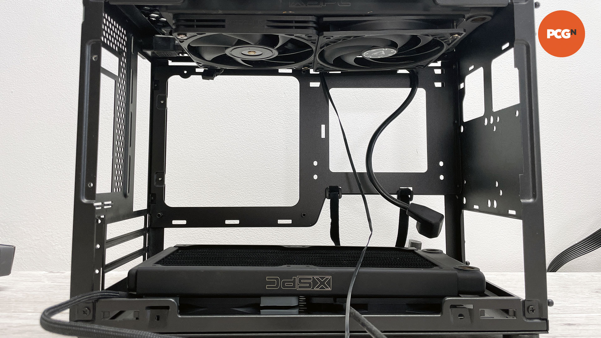
If you’re tweaking your case to make room for new components such as radiators, place these parts into the case where possible so you can work out if your endeavors will work. Here we want to be able to place a radiator in the roof as well as the base of the case.
5. Test-fit motherboard
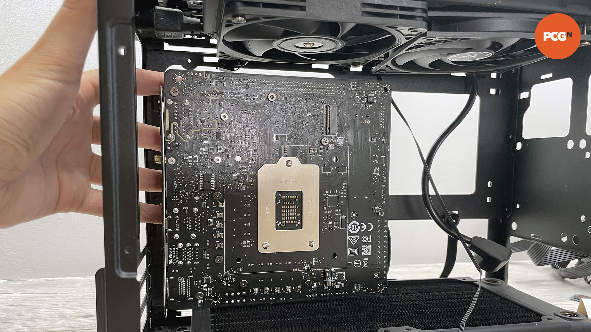
The motherboard’s location will be key, so you need to work out where it needs to sit. In our example, there’s enough space to reside between the radiators, which we’ve checked by test-fitting the motherboard between them.
6. Work out new IO panel location
Work out where your motherboard’s IO panel will be located, as this will dictate the position of the motherboard tray. Use a marker pen to set out where you need the motherboard IO panel cutout to be located.
7. Drill out rivets
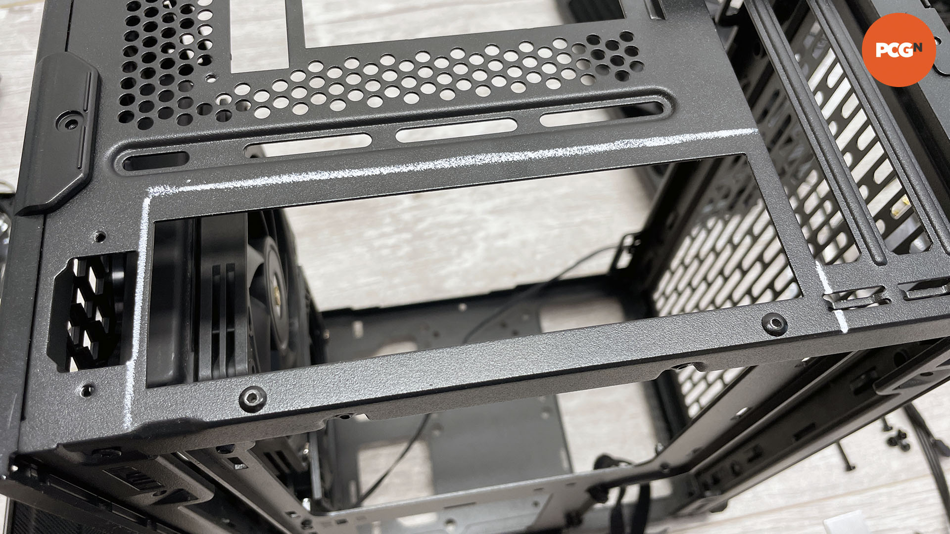
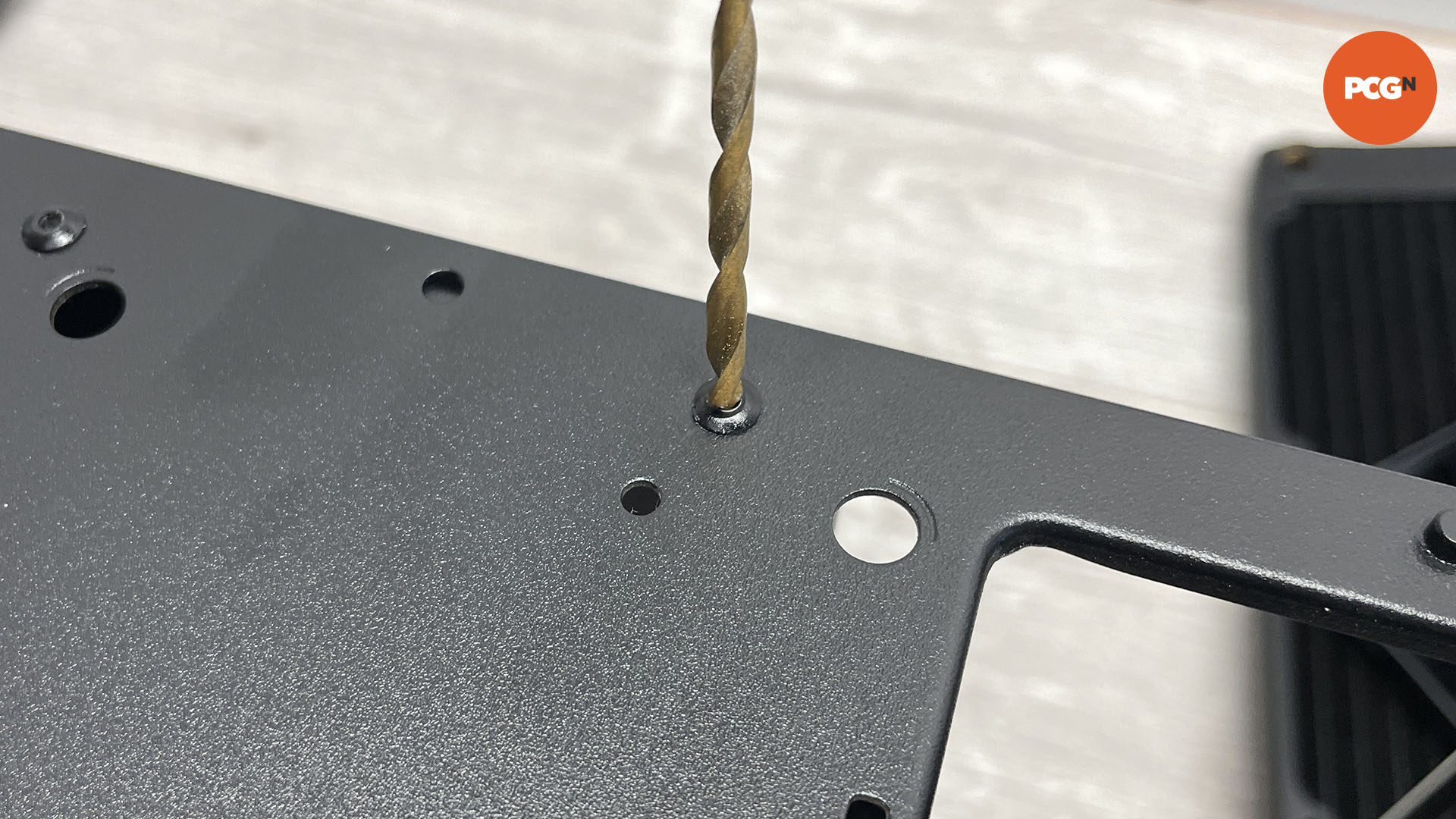
Most cases are held together using rivets, which you’ll need to drill out in order to remove the motherboard tray. Use a 3mm drill bit, as this is the most common rivet size used in cases.
8. Check case components are loose
Once the motherboard tray’s rivets are removed, dislodge the tray at one end to make sure it’s loose. It’s easy to miss a rivet or a securing screw, so if it doesn’t come free easily, check again.
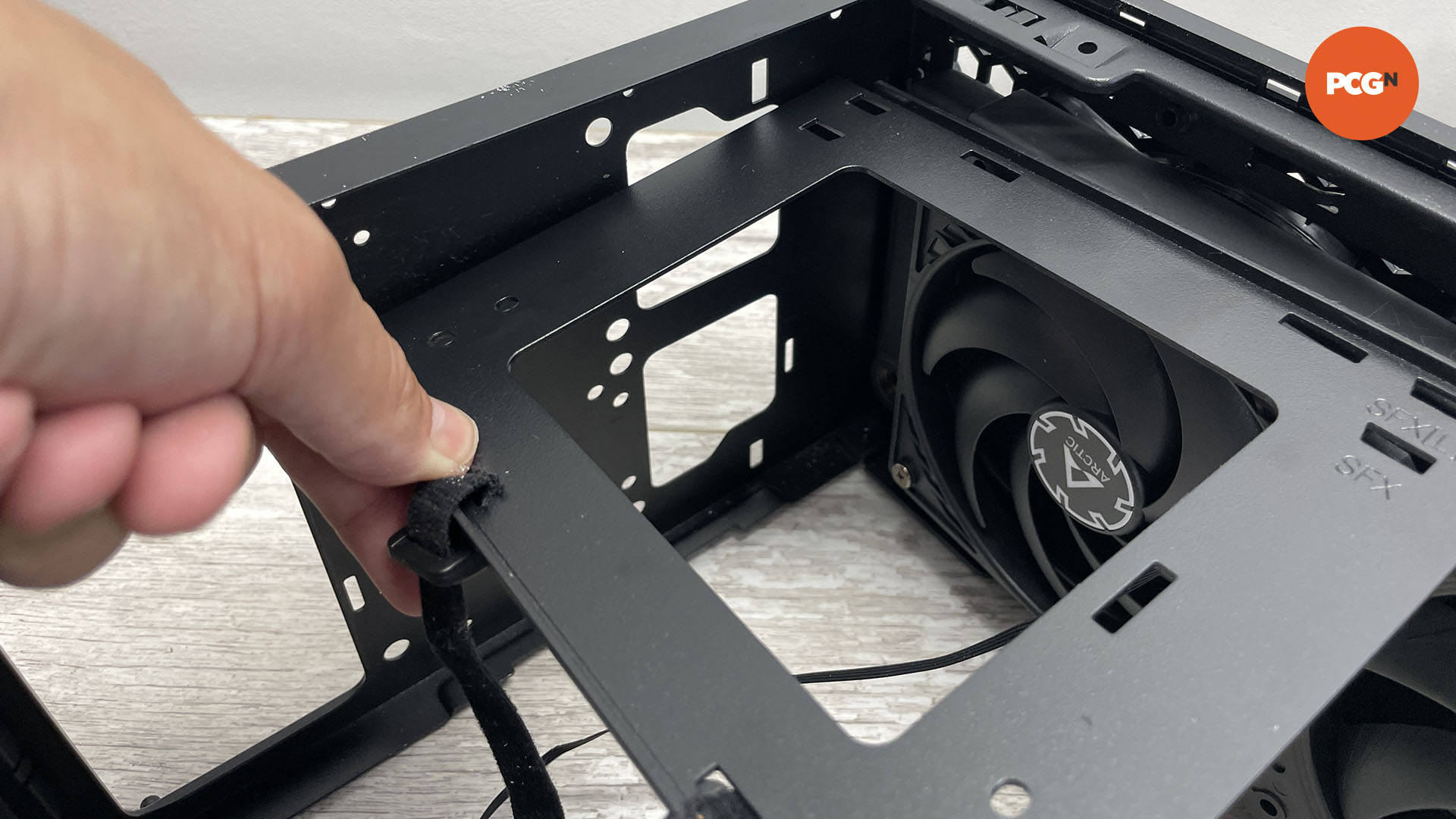
9. Remove motherboard tray
The motherboard tray needs to be removed from the case, so you can adjust its position and alter the rest of the case as necessary. At this point, you also need to think about where to secure it using rivets later.
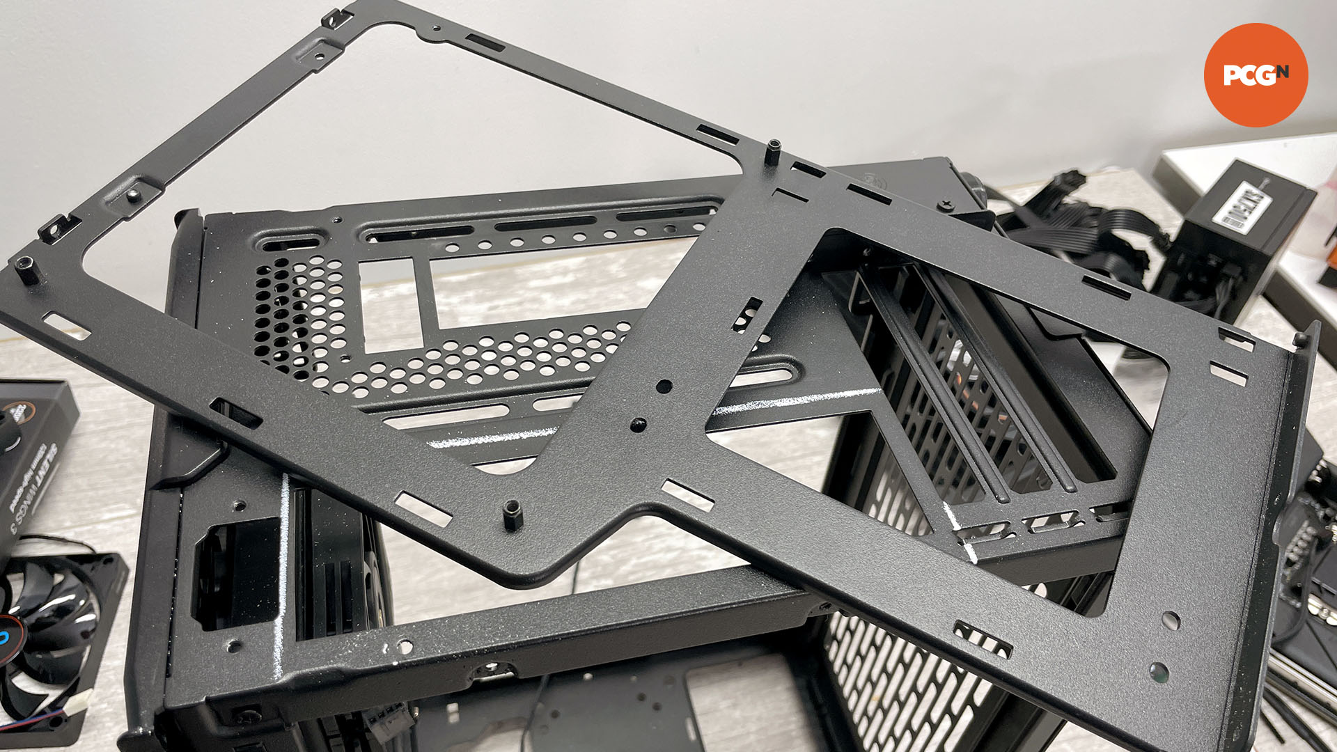
10. Use safety goggles
Before you start cutting, put on a pair of safety goggles. Cutting disks and metal shards can fly off when using power tools so make sure you wear them, even for short jobs.
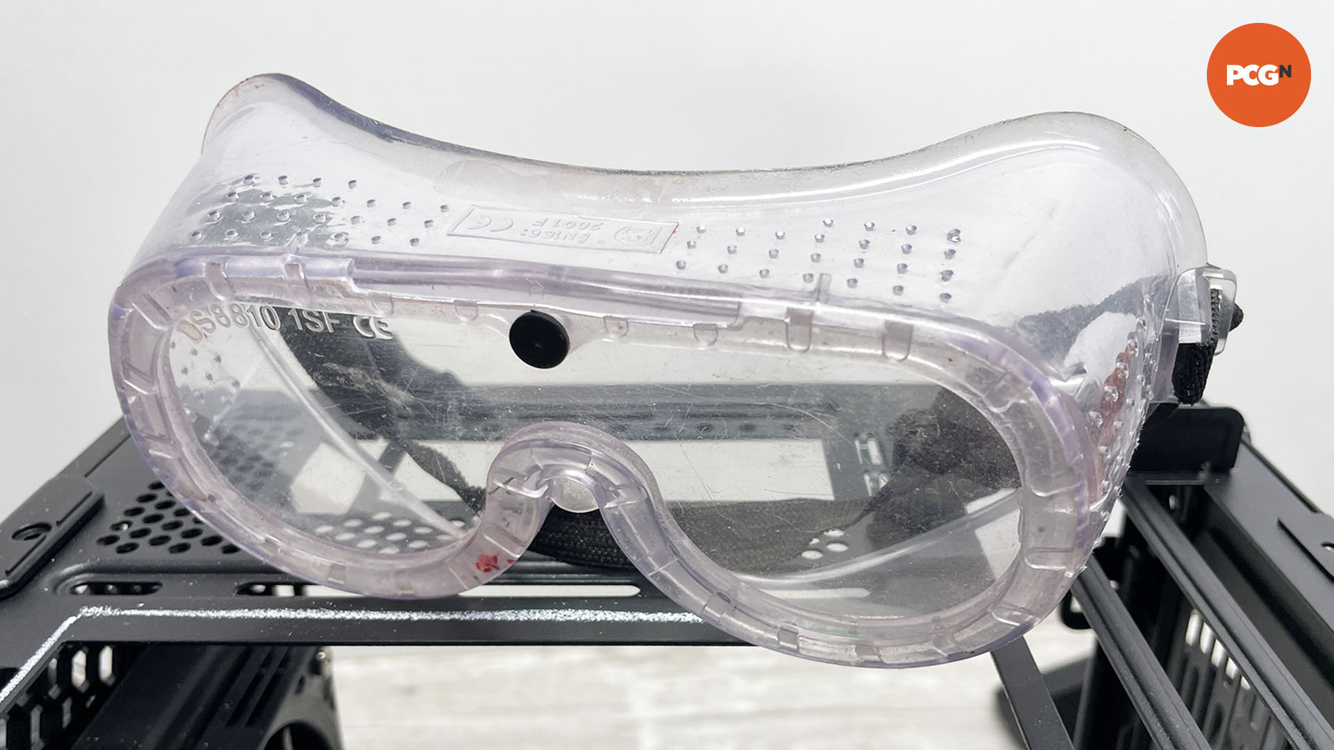
11. Cut out IO panel
Use a rotary tool such as a Dremel and cutting disc to carefully cut out the IO panel area. You’ll need to remove a section with at least 8mm of frame surround in order to reattach the panel to the tray. Alternatively, you can leave it in place and cut a new hole, blanking off the old one with aluminum sheet.
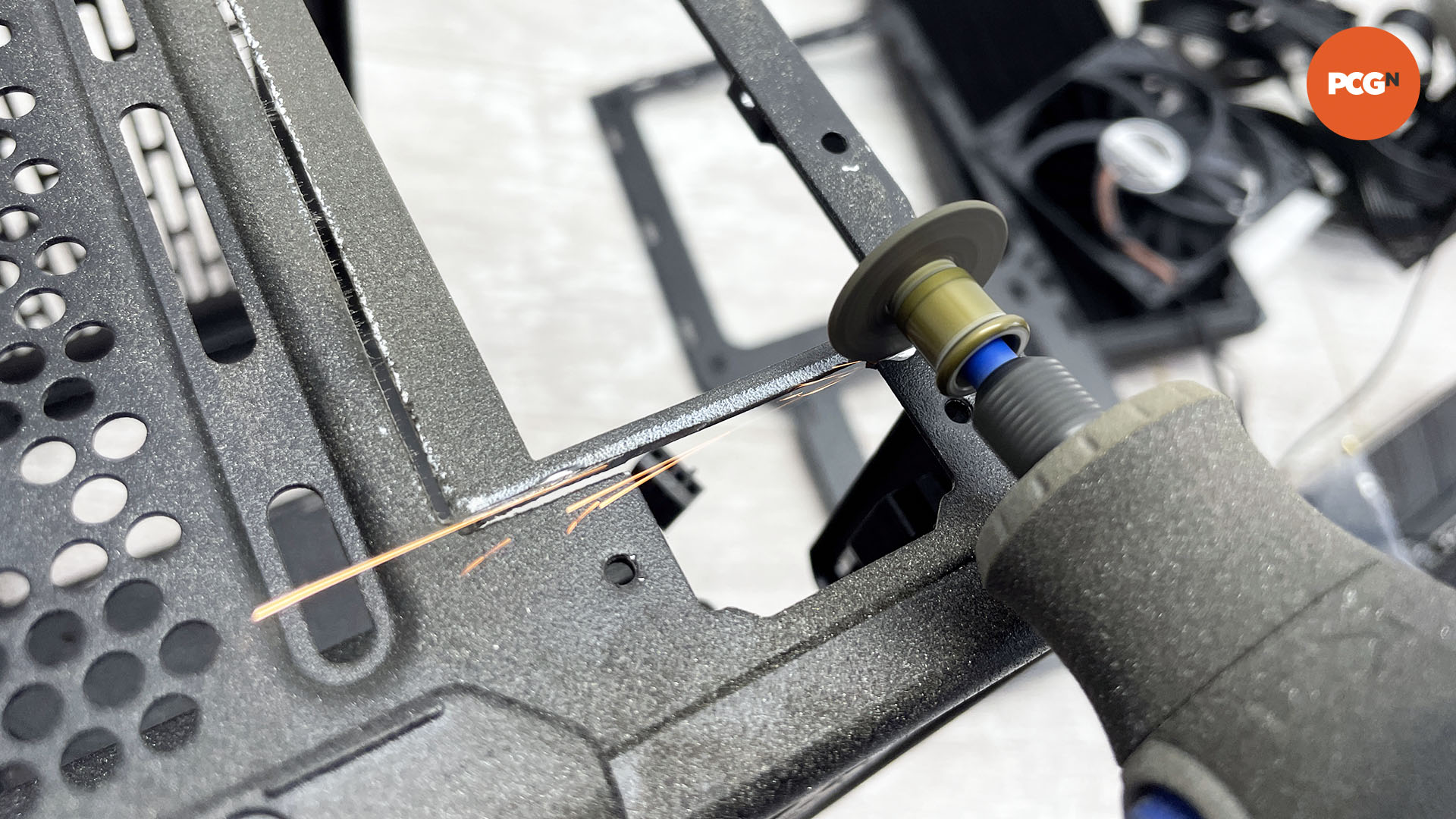
12. Remove IO panel
All cases are different, but we’ve gone with the cut-out method, removing the old IO panel area so we can re-rivet it back onto the motherboard tray.
13. Vacuum dust
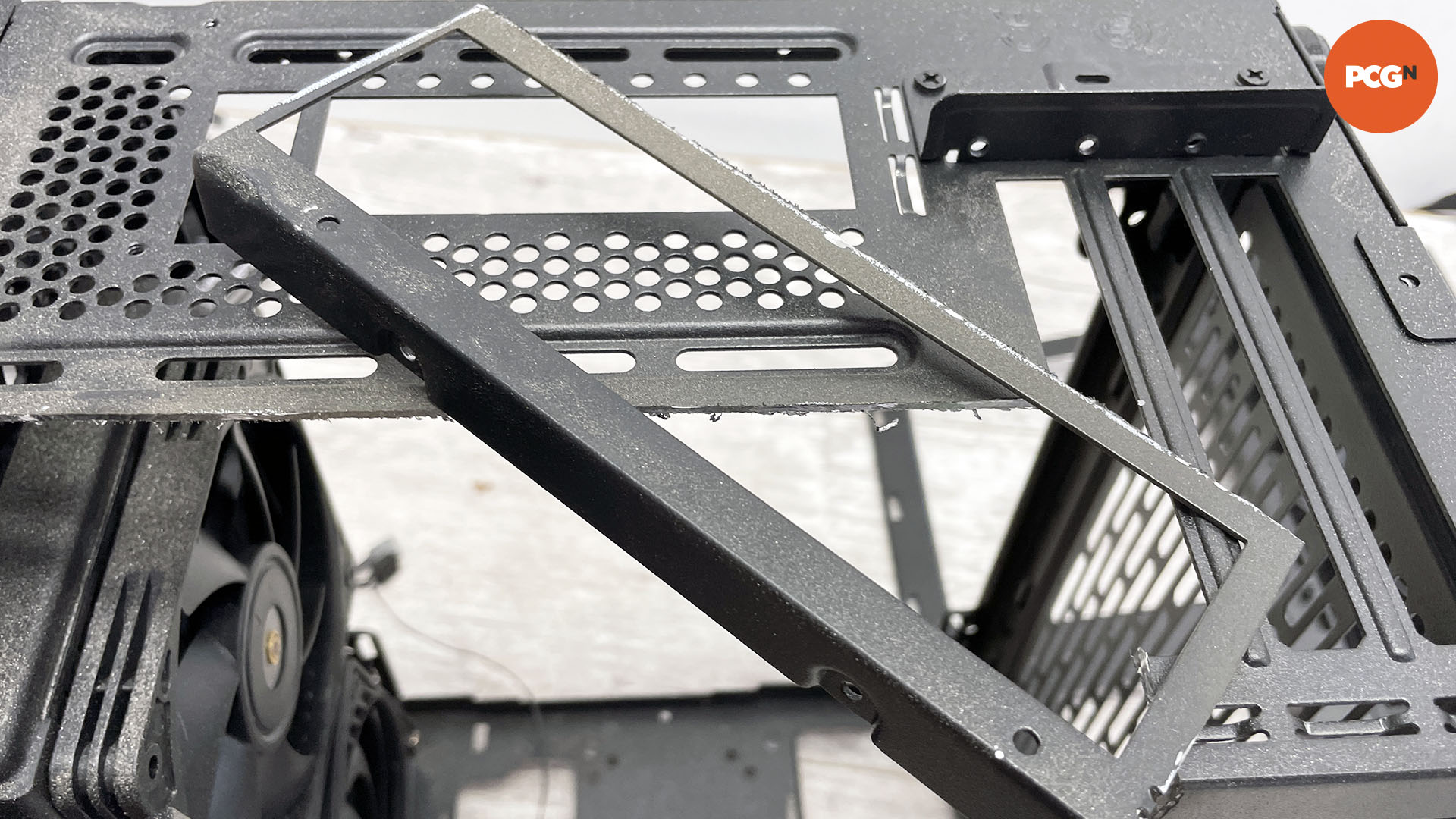
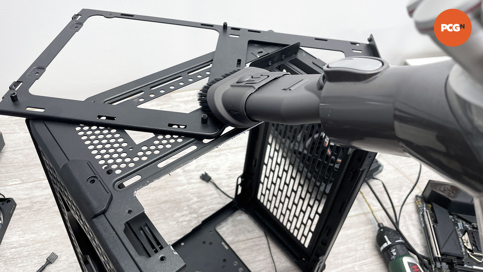
The cutting process will generate a lot of dust, so use a vacuum cleaner as you work, in order to keep your work area clean and tidy.
14. Use the right rivets
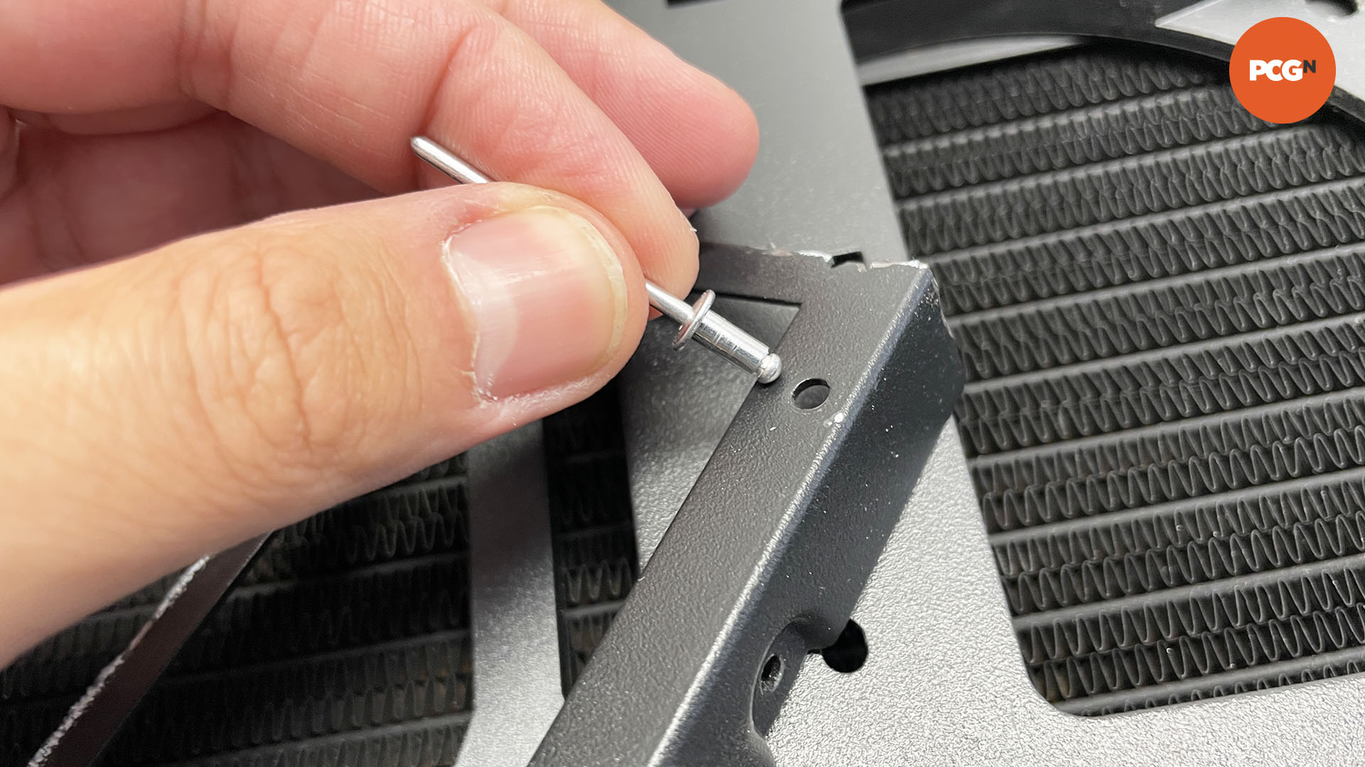
To rivet sections back together, you’ll need to use the correct size rivets. The thick head of the rivet passes through the hole, and this section is the actual width of the rivet. Most cases use 3mm rivets but use a ruler to check the diameter of the holes.
15. Insert rivet into gun
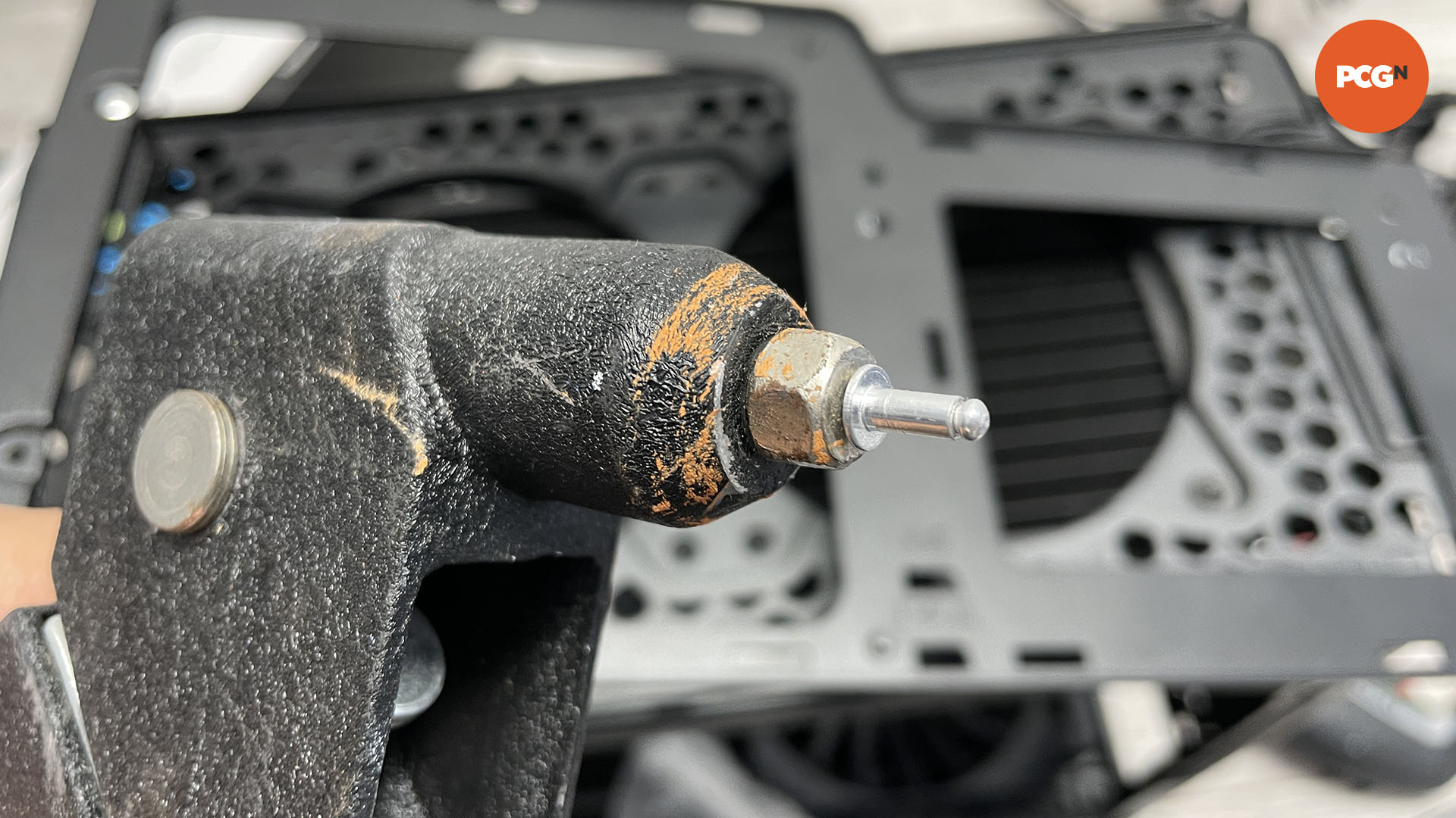
The tail of the rivet is inserted into the rivet gun as shown, so the head pokes out. You then insert the head into the case hole, squeeze the gun’s handle two or three times and this compresses the head and pulls off the tail.
16. Rivet sections back together
Do this with any sections you need to re-attach together. Here we need to reattach the motherboard tray to the IO area we just cut out, so we can then secure both parts to the case in their new position.
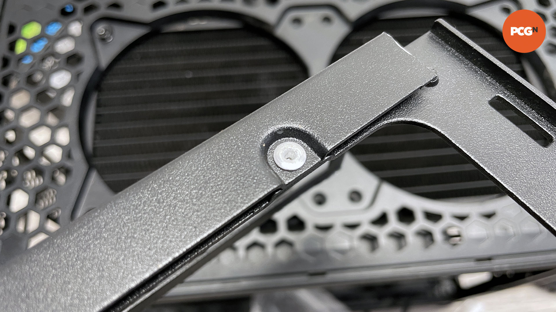
17. Test-fit motherboard
With that done, check if the motherboard sits correctly on the tray and IO panel opening. If you’re rotating and flipping the tray around, it’s easy to make mistakes, but it’s easier to remedy them now than when you’ve used a dozen rivets to reassemble the case.
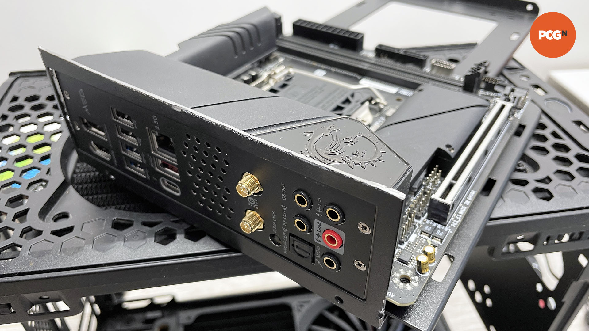
18. Mark up for cutting
We’re cutting a new hole for our motherboard’s IO panel, and to do this we inserted the new motherboard tray and IO panel area into the case to use as a template to mark up the required opening.
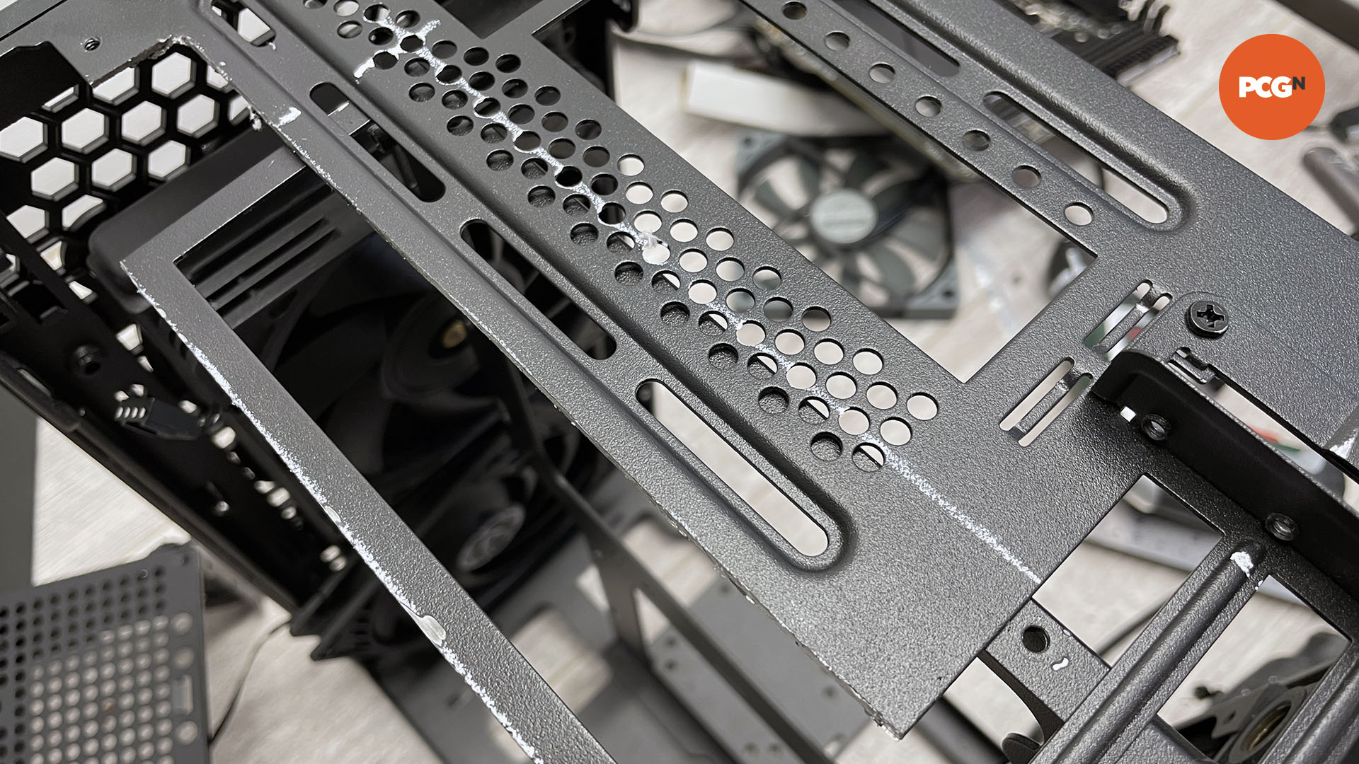
19. Cut IO panel opening
Now go ahead and use your rotary cutting tool to remove the section required, again donning your safety goggles. Focus on cutting straight lines, as this will mean the IO panel section will line up properly.
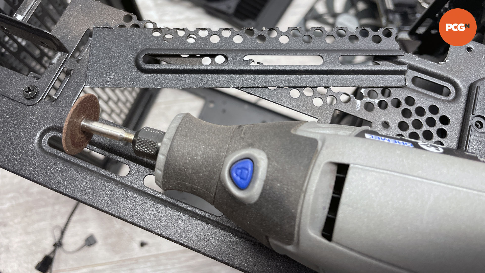
20. Cut away flanges
If there are any metal ridges or flanges in the way of the motherboard tray, you can use the cutting tool to remove them, or alternatively a metal file. We encountered these on one end of the case, which prevented the far end of the tray from sitting flush with the front panel.
21. Create support plate
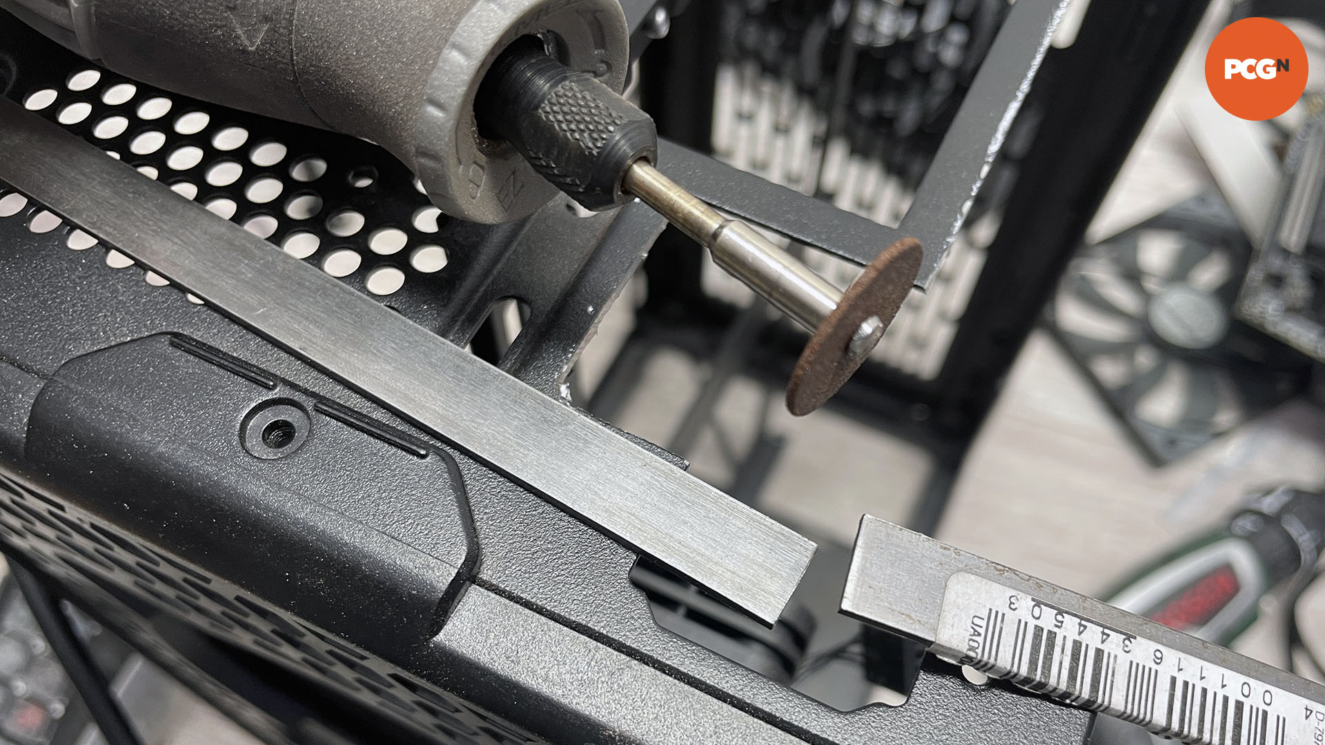
You can use aluminum and steel sheet to close off any gaps and provide extra support for any cut-out sections. Here we’re using 3mm-thick, 10mm-wide steel profile to sit over the back panel to support the motherboard tray. Cut it to length using a hacksaw or rotary cutting tool, so it stretches from top to bottom.
22. Drill support plate
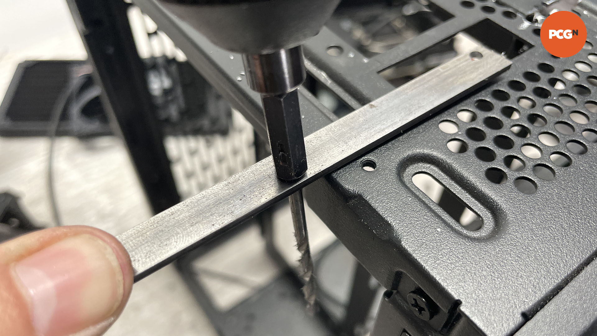
Steel is best used here as it’s stiffer than aluminum. Line it up with any existing holes, or drill new ones through the plate and into the rear of the case and motherboard tray. Use a 3mm drill bit here, so you can use 3mm rivets.
23. Spray paint support plate
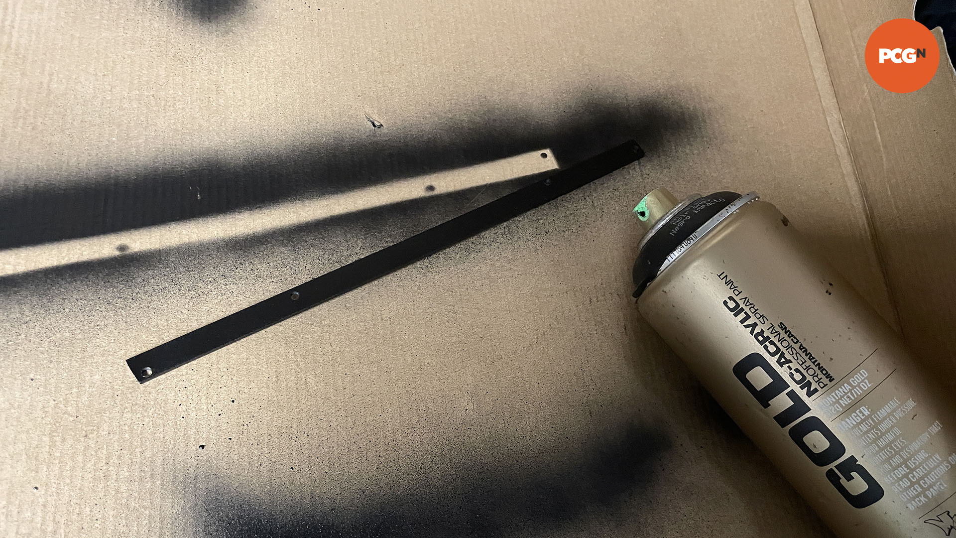
Once the support plate’s modifications are done, you can spray it so it matches the color of your case. Don’t worry about spending too much time preparing the plate. Just place the plate on a spare cardboard sheet and spray each side, allowing each side to dry for an hour before you handle it.
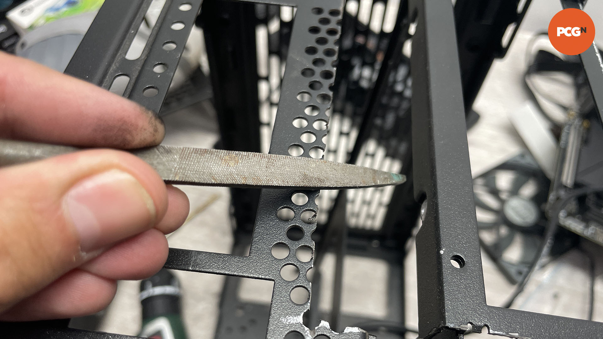
24. File edges
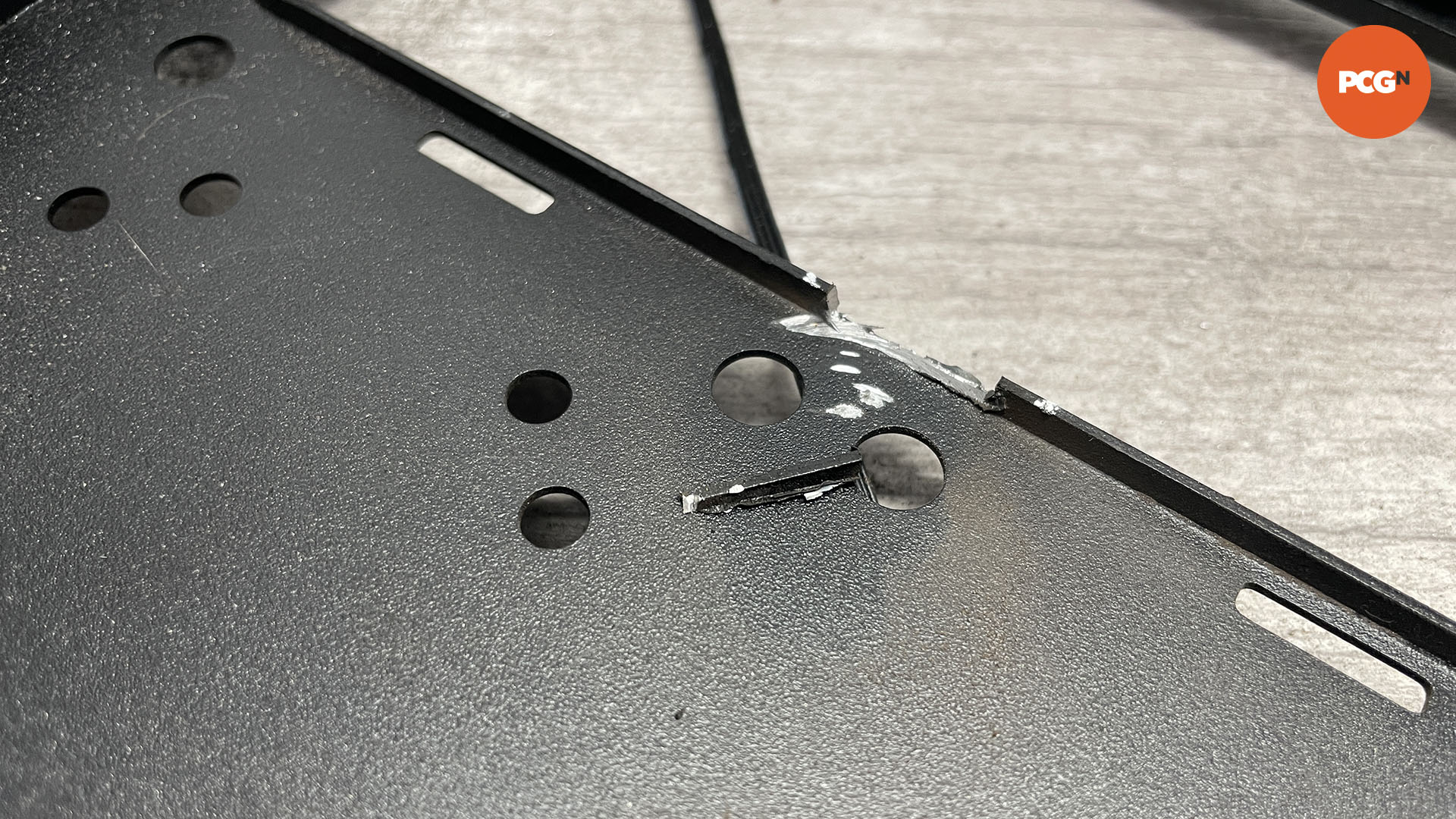
Use a metal file to smooth cut areas on the panels, in order to remove sharp edges or shards. If any visible areas stick out, you can spray paint them so they don’t show. Smaller sections can be hidden using a permanent marker, or by spraying paint into a pool on a piece of cardboard and painting it onto the panel with a small brush.
25. Rivet plate in place
Now fit the support plate to the motherboard tray. If the rivets won’t pass through the metal sheets, use a slightly larger drill bit, for example 3.2mm for a 3mm rivet, as this can sometimes make all the difference.
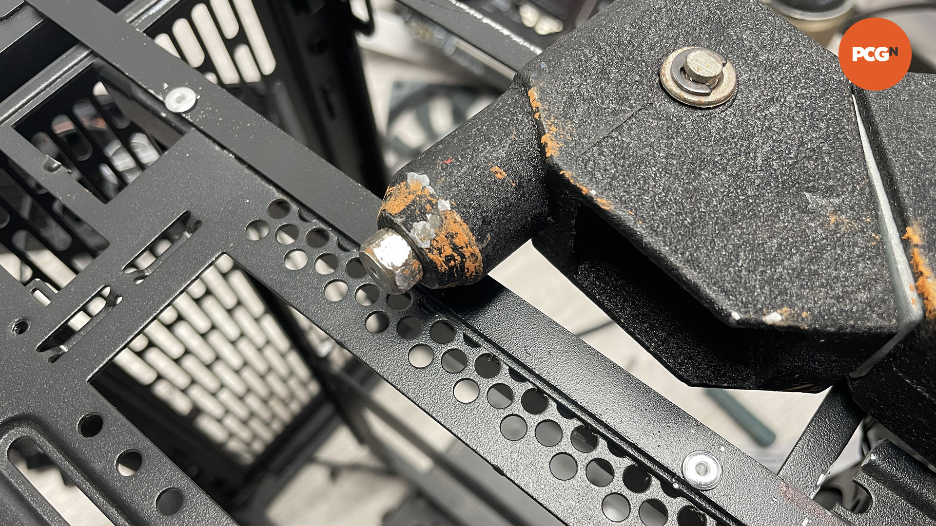
26. Rivet motherboard tray and IO opening
Now add rivets to the rest of the motherboard tray. We’ve added two at the rear and two at the front, securing it to the front and rear panels using the same process as before, drilling 3mm holes in both surfaces and then using rivets.
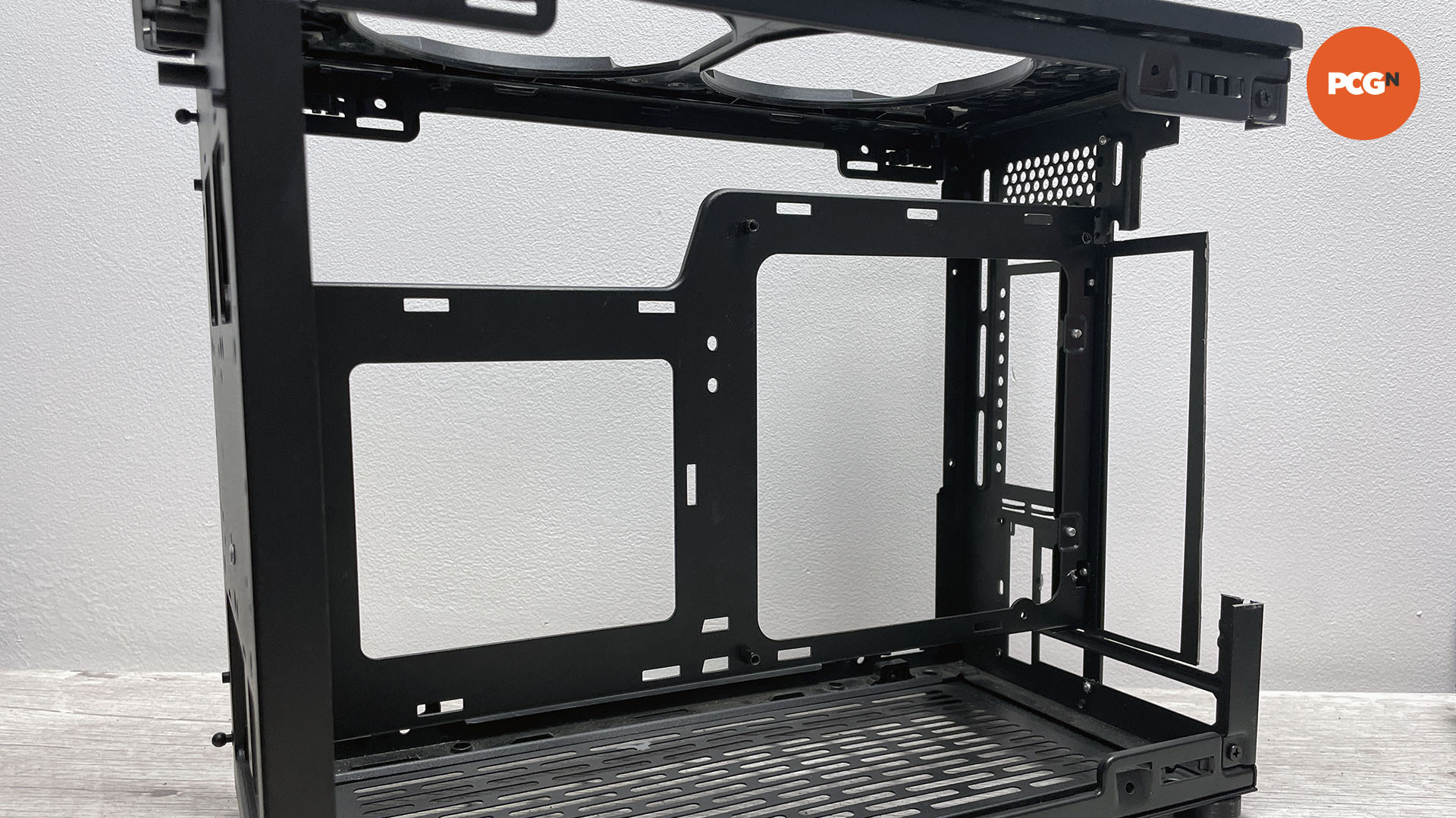
27. Install your hardware
All being well, your hardware can now be installed, but not before a final clean and vacuum. We’ve opened up the case to allow two 240mm radiators to be installed and also created a sandwich layout to make the graphics card and motherboard both visible through the side panels.
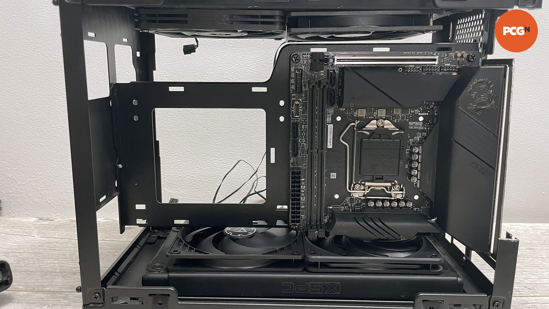
All that’s left for you to do now is install your components in your new case configuration. Meanwhile, if you want to take the above mod further, you could paint your PC case using our full tutorial.
