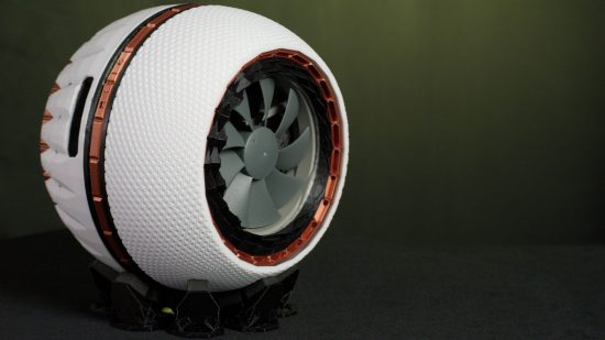
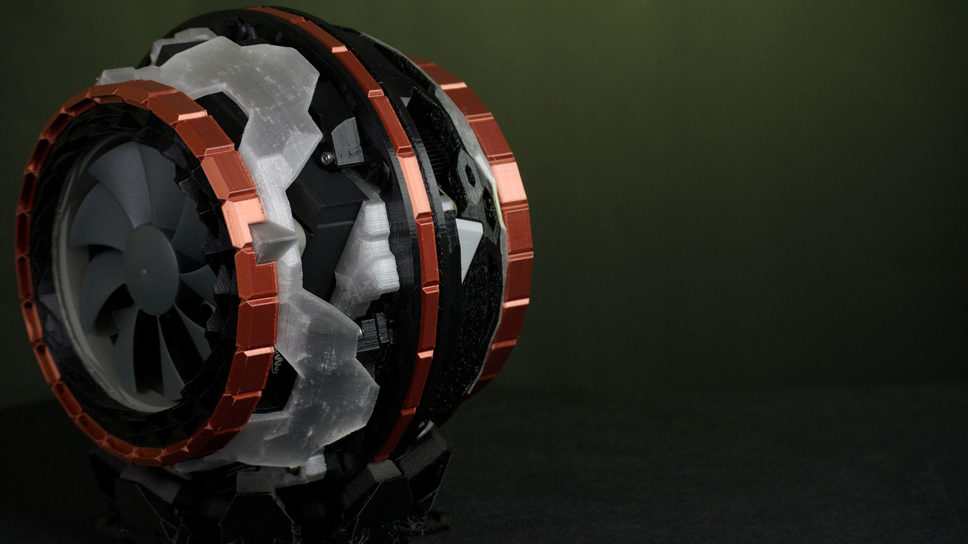
Armed with a modified 3D printer, PC builder Jean Roberto De lacovo created all the parts he needed to make the chassis for this stunning 3D printed PC case. It’s called Piñasphere, and it features a liquid-cooled 8-core AMD Ryzen 7 APU.
Thanks to our rapidly growing PC building Facebook page, we’ve seen many custom gaming PCs, from mods based on existing case designs to scratch builds. You can even submit yours for consideration right here. For now though, let’s find out how Jean made this stunning 3D-printed PC case.
PCGamesN: What inspired you to build this PC?
Jean: I wanted to see how far I could get with the design of a computer case. The standard that people picture in their mind when you talk about a PC is a boxy shape – apart from very few exceptions, most computer cases are based on a square shape.
On the sides you can see these black wavy rings – I wanted them to look like the waves generated when you drop something in water. I was already playing with the pinecone/pineapple motif for the dome at this time, so I thought this idea would work really well for the wave crests too, albeit with a lot of tweaking.
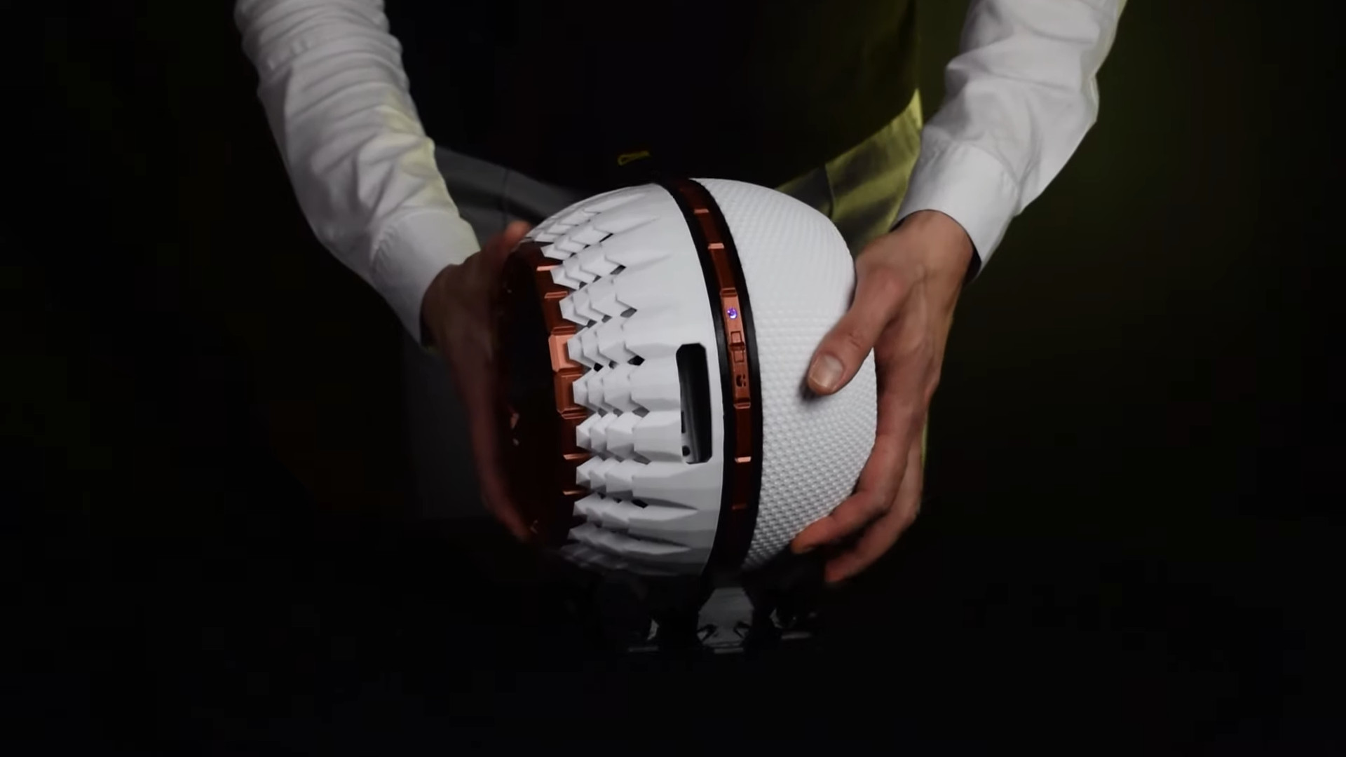
The other half of the dome was also nature-inspired – it’s based on filled honeycombs, and every hexagon is complex when you view it up close. This complexity also helps when it comes to making the printing layer lines less visible. The interior has more of a sci-fi look with lots of polygons. It’s structurally similar to an aircraft frame – it’s not a sphere, but a complex icosphere with geometric holes that help with airflow too.
How did you plan and design this build?
Usually I start my work with some quick pencil and paper sketches, but this one started with a Tinkercad sketch. I was testing various configurations with some 3D mock-ups I made of the hardware components on Tinkercad, then I thought that if I didn’t install a GPU, and used an external PSU, I could try to make a split-sphere shape.
The first idea was to use a handcrafted metal frame made with 3mm-thick aluminum sheet. However, I’d also recently done some experiments with 3D printing to make a camera rig – during those experiments I tested the strength of PLA and PETG, and concluded that PETG was strong enough to handle the stresses of the case.
You used 3D printing for the whole build – tell us all about your process.
At first it was hard, but it would now be a much quicker process, I had to start planning it differently from a usual case mod, because I wasn’t removing material but adding it. I did some tests with different small projects so I could fine-tune the 3D printer settings.
The software I used as a slicer for the prints was Ultimaker Cura 4.13, I found it intuitive from the start and it allowed me to fine-tune my prints. For example, I learned to set the Z-seam alignment to avoid having a visible line on the prints, and to set the retraction settings for different situations – you can basically tailor the settings around your needs.
My workhorse 3D printer is a Creality Ender 3 Pro, which I’ve modded as it was too noisy for me. I’ve added a Creality Silent Mainboard, plus a 120mm fan for the PSU, and I also designed and printed the custom fan ducts for the printer with PETG, which enables me to use a dual 60mm Noctua fan setup instead of the standard 40mm fans.
It also has a direct extruder now – I had to reduce the retraction a lot more than expected, because the first prints with the new setup resulted in extruder clogging problems when printing with PETG.
In total, Piñasphere is composed of 27 3D-printed parts. For the finishing touches I used precision cutters, along with a lighter, to remove any excess material or stringing. However, once I’d got the filament temperatures right I found that stringing was extremely limited.
I also found that the orientation of parts during the printing process helped when it came to finishing. I purposely choose the base as the contact side between parts, as it’s the side with which you have less control for the finish if you don’t paint it afterwards.
One key point I learned is that getting the parts perfectly clean with precision cutters takes time and patience – make one mistake and you end up throwing away the printed part – it happened with an SSD frame I printed. The cleaning and leveling of the printer takes a bit of time too, but it solves the majority of problems that can occur during the printing process – printing at a slower speed also helps avoid a lot of problems.
How do all the pieces fit together?
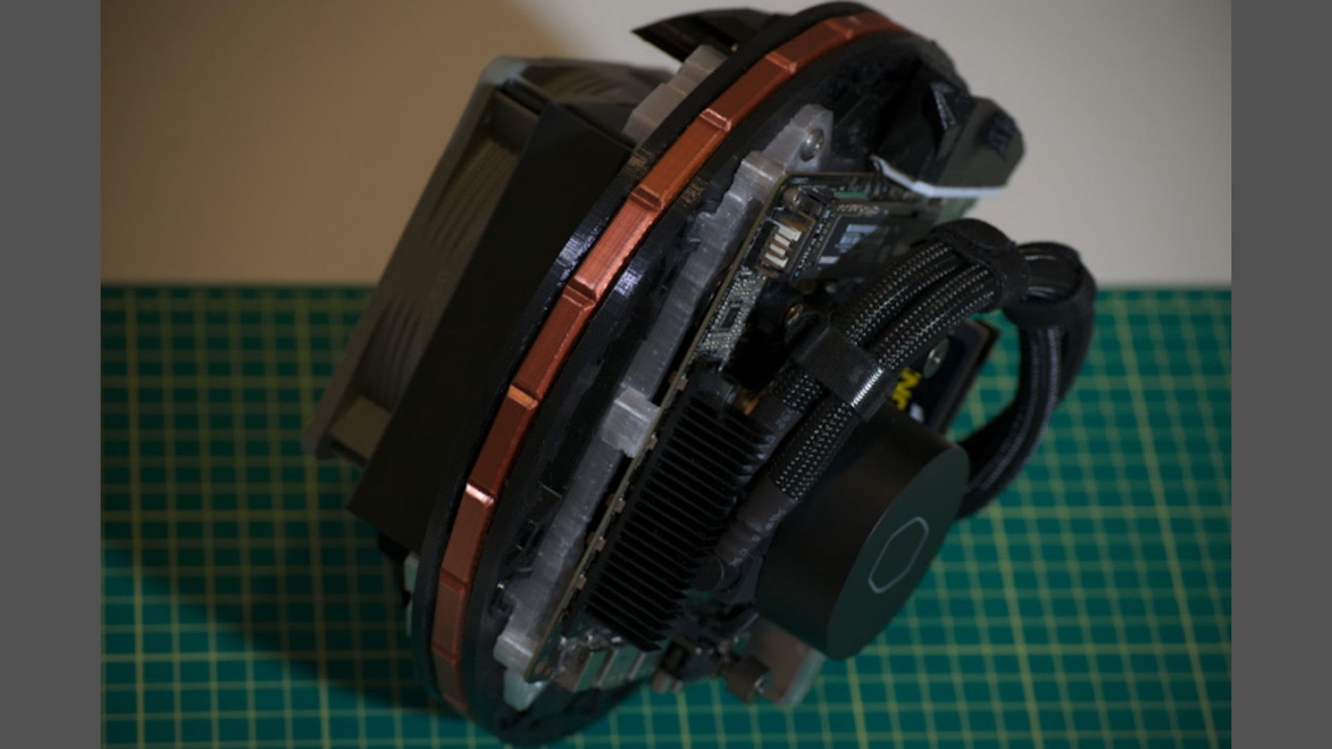
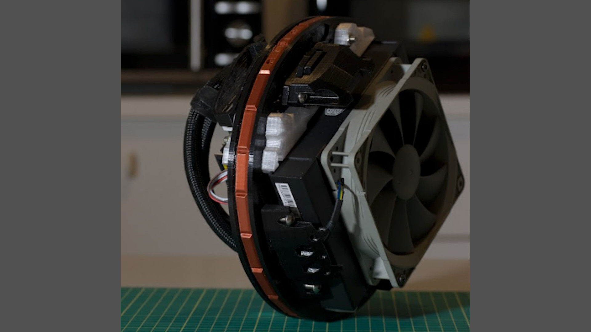
It’s basically a super-sandwich structure – as with aircraft, some parts are simply pressed between the fastened layers. The parts are shaped so they can only be assembled the correct way – even if it’s just a different corner or hole, each part always has an aspect that helps for positioning. This structure enabled me to create a chassis with enough strength, but with minimal infill, so it minimizes the weight and the amount of material used.
I then used stainless steel screws for fastening – the motherboard is secured using M3 screws with 10mm threaded brass inserts – you can warm them up with a soldering iron then press them inside the 3D-printed parts. For the rest of the fastenings, I threaded the PETG with tools and used button-head M5 screws – the threaded sections are at least 10mm long.
Meanwhile, the white domes simply snap into place on the motherboard side, and secure with a slight clockwise twist on the radiator side – no tools are needed here.
What tiny motherboard is that?
I used an ASRock X300M-STX motherboard. It was one of the smallest motherboards I could find that allowed me to use an AMD Ryzen 7 5700G. It can support up to 64GB of memory, and it has two M.2 SSD slots and two SATA ports for 2.5in SSDs, so it gives me ample room to upgrade memory and storage, which will help keep this machine useful in the future, maybe as an office PC or server.
What challenges did the shape of the build present?
Honestly, if you think mostly about the shape and not the dimensions, it’s relatively easy to make a PC with an unusual shape – the biggest challenge for me was leaving enough room inside the case for all the gear to work well.
Another big challenge was presented by the two I/O panels – I’d decided that both of them were going to look like the front panel, placed in a recess of the dome, but I also had to leave some space for the power cord, and that is why the ‘slice’ is so long on that side.
What PSU did you use?
It’s the external power supply that ships with the ASRock Deskmini X300. It looks like a laptop power supply, and its output is 120W at 19V – it’s rather small, so it was perfect for this PC, as it isn’t a power-hungry monster.
How did you plan the cable routing?
All the cables are routed inside the middle ring, which also forms the main frame – it has lots of empty spaces in it for airflow and cable routing. The cables for the power switch, SSD activity LED, and power LED are tucked under the motherboard, and they then go into the box that acts as hooks for the domes and also contains the power switch.
The radiator fan cable is hidden by the dome hook under the radiator – I made a routing canal for it – then it goes through the passage for one of the cooling tubes and stays hidden under the cooling tube on the motherboard side. The Wi-Fi antennae cables are hidden under the motherboard, and their connectors on the top of the motherboard are hidden under the M.2 SSD so you just can’t see them. Lastly, the waterblock cables were laid under the waterblock’s fastening ‘wings’.
Tell us how the airflow system works.
This is one of the parts I like the most in my projects. After going through the radiator, the air goes through the middle channel, cooling the 2.5in SSD, then moves under the motherboard and exits from a 5mm gap between the motherboard and its support frame – it flows around almost the whole perimeter.
But the air isn’t out at this point – the internal dome then guides it to move around the motherboard, so it cools the M.2 modules and motherboard VRM heatsink. There are also two holes on the side of the radiator, which relieve a bit of the counter pressure generated from the air moving inside the middle channel.
How did you achieve the copper-colored touches?
I wanted to add a warm color to contrast against the white, and I originally considered using real copper rings. However, during the sketching phase I wanted to add more reflective facets than you get on rings, so I printed them with a more complex shape.
If I’d had a tonne of time I could have handcrafted them, but this time I wanted to test myself and see what I could do with just 3D printing, so I bought some Giantarm Silk Copper Filament and the results didn’t disappoint – they do give a premium vibe to the build.
What spec did you choose and why?
I wanted it to be able to do a bit of everything, but 3D editing was a must-have capability. I also wanted the machine to perform decently at 1080p gaming. With no room for a graphics card, the obvious choice was going for the best APU I could buy, and that was the AMD Ryzen 7 5700G – I love it; it’s an excellent performer.
The build has 16GB of memory, because I was looking for the hardware during October and November, and it was on sale then. Corsair is a good brand, so I took my chance and bought it.
I will upgrade the RAM in the next few months, as the ASRock motherboard allows you to increase the shared video RAM up to 16GB if you have more than 32GB of system memory.

Did you come across any difficulties?
I think the biggest challenge was fine-tuning the printer profile for every filament. I had to reduce the printing errors that would be impossible to hide, as one of my objectives was to make the build look good without having to paint it.
I got used to deep-cleaning the extruder, and I also bought a long stainless steel needle to purge every bit of filament residue out of it.
How long did it take you to complete this build, from start to finish?
After the learning about 3D editing phase, I would say 3-4 months. It would definitely take less time if I did it now.
Are you completely happy with the end result, or do you wish you’d done some of it differently in retrospect?
I’m absolutely happy – this was the first time I’d tried building a 3D-printed case, and before the final assembly I wasn’t 100% sure how it would look. However, after I assembled it all together I had only one thought – ‘Wow, it’s solid and looks really cool!’ I really couldn’t be happier.

Pinasphere 3D-printed PC specs
- CPU: AMD Ryzen 7 5700G
- GPU: Integrated AMD Radeon RX Vega11
- Storage: 1TB Samsung 980 M.2 SSD, 250GB Samsung 860 Evo 2.5in SATA SSD
- Memory: 16GB (2 x 8GB) Corsair Vengeance 3200MHz DDR4 SODIMMs
- Motherboard: ASRock X300 M-STX
- PSU: 120W ASRock external PSU
- Cooling: Cooler Master MasterLiquid ML120L V2 AIO liquid cooler
Amazing work, Jean. This is a truly one-of-a-kind custom PC – the design is outstanding, and you’ve also shown that you really can make a damn good-looking 3D-printed PC case as well.
This post originally appeared on Custom PC, which has been covering amazing setups for over 20 years and is now part of PCGamesN. Join our 500k member Facebook group to discuss this build.
If you consider yourself to be an expert PC builder, you can submit your own custom PC build to us today for a chance of being featured on PCGamesN in the future.
